I have writeATMEga8535 & Arduino IDE, its time to try how will it works. This time I’d like to try using Timer Interrupt. Will be usefull for time critical (e.g dot matrix scanning) and PWM generation.
First step, open BareMinimum on File>Example>Basic and place this code in the setup routines (just after void setup() {):
// initialize timer1

noInterrupts();           // disable all interrupts

TCCR1A = 0;

TCCR1B = 0;

TCNT1  = 0;
  OCR1A = 31250;            // compare match register 16MHz/256/2Hz

TCCR1B |= (1 << WGM12);   // CTC mode

//TCCR1B |= (1 << CS11);    // 8 prescaler

TCCR1B |= (1 << CS10);    // 64 prescaler (overide) or no prescaler (standalone)

TIMSK |= (1 << OCIE1A);  // enable timer compare interrupt /TIMSK1

interrupts();             // enable all interrupts
That was initialization for Timer1 which is 16bit timer. The important thing to do are disable interrupt vector and re-enable interupt vector after timer initialization done.
TCCR1A (Timer/Counter1 Control Register A) is register consist of WGM (Wave Generation Mode) to decide what mode which we will use. There are 4 main modes, Normal, CTC, PWM and Fast PWM mode. This time i’d prefer CTC mode.

In CTC (Clear Timer on Compare) mode the counter will count until it hits the value specified in the OCR1 register. When the TCNT1 passes the TOP value (Specified by the OCR1) it resets to 0 and at the same time sets the TOV1 flag.
Look at following table, what we need to set is only WGM12 to be 1 (mode 4).

But wait! What is the difference between mode 4 and mode 12? Yes, Register that used to manipulate the counter resolution is OCR1A for CTC mode 4, mean while CTC mode 12 use ICR1. The ICR1 Register is not double buffered. This means that if ICR1 is changed to a low value when the counter is running with a low or none prescaler value, there is a risk that the new ICR1 value written is lower than the current value of TCNT1. The result will then be that the counter willmiss the Compare Match at the TOP value. The OCR1A Register however, is double buffered. This feature allows the OCR1A I/O location to be written anytime.
When the OCR1A I/O location is written the value written will be put into the OCR1A Buffer Register. The OCR1A Compare Register will then be updated with the value in the Buffer Register at the next timer clock cycle the TCNT1 matches TOP. The update is done at the same timer clock cycle as the TCNT1 is cleared and the TOV1 Flag is set.
Using the ICR1 Register for defining TOP works well when using fixed TOP values. By using ICR1, the OCR1A Register is free to be used for generating a PWM output on OC1A. However, if the base PWM frequency is actively changed (by changing the TOP value), using the OCR1A as TOP is clearlya better choice due to its double buffer feature.
Next step is reseting Timer 1 Counter in TCNT1 Register. TCNT1 is the counter register which is increasing when timmer is running.
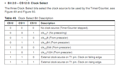
To make timer work, prescales have to be set either internal or external clock source. Prescaler can be set in TCCR1B Register at CS12;CS11;CS10.
To user timer1 as interrupt, TIMSK Register have to be set. When OCIE1A bit is written to one, and the I-flag in the Status Register is set (interrupts globally enabled), the Timer/Counter1 Output Compare A Match interrupt is enabled. The corresponding Interrupt Vector is executed when the OCF1A Flag, located in TIFR, is set.
Don’t forget to re-enable Interrupt to get TImer1 Interrupt work.