Panduan cepat untuk mengekspor desain PCB dari Eagle dan mengimpornya ke FlatCAM. Panduan ini dibuat dengan Eagle versi 7.2.0 Light dan FlatCAM 8.2.
Sebagian besar desain dimulai dengan skema rangkaian:
Kemudian dengan meng-klik File→Switch to board, editor papan PCB terbuka dan kemudian menyelesaikan tata letak rangkaian:
Untuk ekspor file cam bor, buka File→CAM Processor lagi dan pilih setelan pada gambar di bawah. Pilih EXCELLON_24 untuk bagian Device. Berikan ekstensi drills.drd pada nama file bor jika perlu. Klik Proses Job untuk mengekspor.
Kita sudah selesai dengan Eagle. Sekarang mari beralih ke FlatCAM.
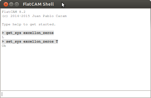
Eagle menggunakan Trailing Zeros dalam format angka Excellon, format ini perlu dilaporkan dengan benar di FlatCaM dengan cara berikut:
Perubahan pada opsi sistem akan disetel saat memulai ulang, maka FlatCam perlu dijalankan ulang.
Sekarang cukup buka file Gerber dan Excellon yang diekspor dari Eagle.
Cara setting flatmac dapat dilihat di artikel berikut:
This can be done directly from the webinterface. Just go to Plugins -> Plugin Editor -> select the Plugin SyntaxHighlighter Evolved -> add the snippet to the end
//File: Serial.h
#ifndef SERIALCLASS_H_INCLUDED
#define SERIALCLASS_H_INCLUDED

#include <windows.h>
#include <stdio.h>
#include <stdlib.h>

class Serial
{
    private:
        //Serial comm handler
        HANDLE hSerial;
        //Connection status
        bool connected;
        //Get various information about the connection
        COMSTAT status;
        //Keep track of last error
        DWORD errors;

    public:
        //Initialize Serial communication with the given COM port
        Serial(char *portName);
        //Close the connection
        ~Serial();
        //Read data in a buffer, if nbChar is greater than the
        //maximum number of bytes available, it will return only the
        //bytes available. The function return -1 when nothing could
        //be read, the number of bytes actually read.
        int ReadData(char *buffer, unsigned int nbChar);
        //Writes data from a buffer through the Serial connection
        //return true on success.
        bool WriteData(char *buffer, unsigned int nbChar);
        //Check if we are actually connected
        bool IsConnected();


};

#endif // SERIALCLASS_H_INCLUDED
//File: Serial.cpp
#include "Serial.h"

Serial::Serial(char *portName)
{
    //We're not yet connected
    this->connected = false;

    //Try to connect to the given port throuh CreateFile
 #if _MSC_VER && !__INTEL_COMPILER
    const size_t cSize = strlen(portName) + 1;
    wchar_t* wc = new wchar_t[cSize];
    mbstowcs_s(NULL, wc, cSize, portName, cSize);
    this->hSerial = CreateFile(wc,
        GENERIC_READ | GENERIC_WRITE,
        0,
        NULL,
        OPEN_EXISTING,
        FILE_ATTRIBUTE_NORMAL,
        NULL);
#else
    //Try to connect to the given port throuh CreateFile
    this->hSerial = CreateFile(portName,
        GENERIC_READ | GENERIC_WRITE,
        0,
        NULL,
        OPEN_EXISTING,
        FILE_ATTRIBUTE_NORMAL,
        NULL);
#endif

    //Check if the connection was successfull
    if(this->hSerial==INVALID_HANDLE_VALUE)
    {
        //If not success full display an Error
        if(GetLastError()==ERROR_FILE_NOT_FOUND){

            //Print Error if neccessary
            printf("ERROR: Handle was not attached. Reason: %s not available.\n", portName);

        }
        else
        {
            printf("ERROR!!!");
        }
    }
    else
    {
        //If connected we try to set the comm parameters
        DCB dcbSerialParams = {0};

        //Try to get the current
        if (!GetCommState(this->hSerial, &dcbSerialParams))
        {
            //If impossible, show an error
            printf("failed to get current serial parameters!");
        }
        else
        {
            //Define serial connection parameters for the arduino board
            dcbSerialParams.BaudRate=CBR_9600;
            dcbSerialParams.ByteSize=8;
            dcbSerialParams.StopBits=ONESTOPBIT;
            dcbSerialParams.Parity=NOPARITY;
            //Setting the DTR to Control_Enable ensures that the Arduino is properly
            //reset upon establishing a connection
            dcbSerialParams.fDtrControl = DTR_CONTROL_ENABLE;

             //Set the parameters and check for their proper application
             if(!SetCommState(hSerial, &dcbSerialParams))
             {
                printf("ALERT: Could not set Serial Port parameters");
             }
             else
             {
                 //If everything went fine we're connected
                 this->connected = true;
                 //Flush any remaining characters in the buffers
                 PurgeComm(this->hSerial, PURGE_RXCLEAR | PURGE_TXCLEAR);
                 //We wait 2s as the arduino board will be reseting
                 Sleep(2000);
             }
        }
    }

}

Serial::~Serial()
{
    //Check if we are connected before trying to disconnect
    if(this->connected)
    {
        //We're no longer connected
        this->connected = false;
        //Close the serial handler
        CloseHandle(this->hSerial);
    }
}

int Serial::ReadData(char *buffer, unsigned int nbChar)
{
    //Number of bytes we'll have read
    DWORD bytesRead;
    //Number of bytes we'll really ask to read
    unsigned int toRead;

    //Use the ClearCommError function to get status info on the Serial port
    ClearCommError(this->hSerial, &this->errors, &this->status);

    //Check if there is something to read
    if(this->status.cbInQue>0)
    {
        //If there is we check if there is enough data to read the required number
        //of characters, if not we'll read only the available characters to prevent
        //locking of the application.
        if(this->status.cbInQue>nbChar)
        {
            toRead = nbChar;
        }
        else
        {
            toRead = this->status.cbInQue;
        }

        //Try to read the require number of chars, and return the number of read bytes on success
        if(ReadFile(this->hSerial, buffer, toRead, &bytesRead, NULL) && bytesRead != 0)
        {
            return bytesRead;
        }

    }

    //If nothing has been read, or that an error was detected return -1
    return -1;

}


bool Serial::WriteData(char *buffer, unsigned int nbChar)
{
    DWORD bytesSend;

    //Try to write the buffer on the Serial port
    if(!WriteFile(this->hSerial, (void *)buffer, nbChar, &bytesSend, 0))
    {
        //In case it don't work get comm error and return false
        ClearCommError(this->hSerial, &this->errors, &this->status);

        return false;
    }
    else
        return true;
}

bool Serial::IsConnected()
{
    //Simply return the connection status
    return this->connected;
}
Berikut contoh koneksi pengiriman data
#include <iostream>
#include "windows.h"
#include "Serial.h"

#include <thread>
#include <chrono>

using namespace std;

void delay(int ms){
    std::this_thread::sleep_for (std::chrono::milliseconds(ms));
}

int main(int argc, char** argv) {

    char alamatPort[] = "\\\\.\\COM7";
    Serial* s = new Serial(alamatPort);

	char dataOn[256] = "on1\n"; //"Nyala!";
	char dataOff[256] = "off0\n"; //"mati!";

	cout<<"isikan angka 1 untuk menyalakan, atau 0 untuk mematikan"<<endl;


	int jawab;
	do{
        cin>>jawab;;

        if(jawab==0)
            s->WriteData(dataOff, sizeof(dataOff));
        if(jawab==1)
            s->WriteData(dataOn, sizeof(dataOn));
        if(jawab==2)
            for(int a=0;a<5;a++){
                s->WriteData(dataOn, sizeof(dataOn));
                delay(500);
                s->WriteData(dataOff, sizeof(dataOff));
                delay(500);
            }
	}while(jawab<3);

	return 0;
}
Berikut contoh untuk mengirim dan menerima data
#include <iostream>
#include <stdio.h>
#include <tchar.h>
#include "Serial.h" // Library described above
#include <string>


/* run this program using the console pauser or add your own getch, system("pause") or input loop */
char alamatPort[] = "\\\\.\\COM7";
Serial* SP = new Serial(alamatPort);    // adjust as needed

void* baca(void* data)
{

    char incomingData[256] = "";            // don't forget to pre-allocate memory
    //printf("%s\n",incomingData);
    int dataLength = 256;
    int readResult = 0;


    while (SP->IsConnected())
    {
        readResult = SP->ReadData(incomingData, dataLength);
        if (readResult > 0) {
            printf("%s\n", incomingData);
        }
        //printf("Bytes read: (-1 means no data available) %i\n",readResult);

        //std::string test(incomingData);

        //printf("%s",incomingData);
        //test = "";

        Sleep(500);
    }
    return NULL;
}

void* tulis(void* data)
{
    while (SP->IsConnected())
    {
        char outgoingData[256] = "";
        char keluar[256] = "keluar";
        int dataLength = sizeof(outgoingData);        // don't forget to pre-allocate memory
        scanf_s("%255s", outgoingData, dataLength);

        if (outgoingData != "")
        {
            if (strcmp(outgoingData, "OK") == 0) {
                printf("Pengiriman selesai\n");
                return NULL;

            }
            if (SP->WriteData(outgoingData, dataLength))
            {
                printf("Data send:%s\n", outgoingData);
            }
        }

        Sleep(500);
    }
    // do stuff...
    return NULL;
}

#if _MSC_VER && !__INTEL_COMPILER
#include <thread>

int main(int argc, char** argv) {
    printf("Welcome to the serial test app!\n\n");
    if (SP->IsConnected())
        printf("Serial sudah terhubung\n");
    int status;
    std::thread thrd_1(baca,(void*)0);
    std::thread thrd_2(tulis, (void*)0);

    thrd_1.join();
    thrd_2.join();

}
#else
// thread example
#include <pthread.h>

int main(int argc, char** argv) {
    printf("Welcome to the serial test app!\n\n");
    if (SP->IsConnected())
        printf("Serial sudah terhubung\n");

    pthread_t thrd_1;
    pthread_t thrd_2;
    int status;

    pthread_create(&thrd_1, NULL, baca, (void*)0);
    pthread_create(&thrd_2, NULL, tulis, (void*)0);

    pthread_join(thrd_1, (void**)&status);
    pthread_join(thrd_2, (void**)&status);

    printf("Terima kasih");

    return 0;
}
#endif
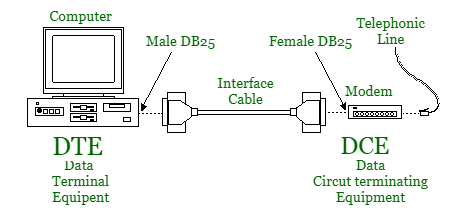
DTE adalah Data Terminal Equipment, dimana sumbaer data dan pengolahannya ada di bagian ini. Untuk koneksi SPI ini dinamakan Master. Sedangkan DCE atau Data Circuit terminating Equipment adalah perangkat periferal dari DTE. Ini dinamakan Slave pada antarmuka SPI.
DTE dan DCE
Gender koneksi DTE dibanding DCE
Pada koneksi DTE dalam banyak kasus biasanya jenis MALE, sedangkan untuk DCE adalah yang female. Namun tidak semuanya seperti ini, harus pintar membaca petunjuk atau datasheet.
Male untuk DTE dan Female untuk DCE
Pinout
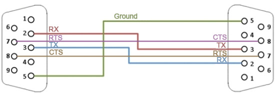
Untuk koneksi RS232 dasar, biasanya hanya perlu Rx, Tx dan Ground. Beberapa peralatan mungkin memerlukan pin kontrol tambahan. Berikut bagaimana pengaturan pin menempatkan Tx ke Rx, DTR ke DSR, dan RTS ke CTS.
Pinout DB9 pada RS232 untuk Male (DTE) dan Female (DCE)
Contoh modul untuk DTE dan DCE
Modul untuk DCE dengan konektor Female
Modul untuk DTE dengan konektor Male
Null Modem
Null modem dibutuhkan untuk koneksi DTE ke DTE (Male – Male) atau DCE ke DCE (Female-Female)
Saat ukuran desain PCB kecil, katakanlah 2×3 cm, dan akan dibuat pada PCB dengan ukuran 10 x 10 cm, maka desain PCB dapat dibuat panel. PCB ukuran 10 x 10 akan dapat menampung setidaknya 12 desain PCB 2×3 cm.
Buka pada Panel Properties dan isikan ukuran PCB 100mm x 100mm. Tentukan jarak antar desain PCB 2mm.
Buka folder gerber pada menu Add Gerber Folder
kanan pada instance lalu pilih menu Add Instance. Lakukan 11 kali, hingga instance menjadi 12.
Pilih Autopack agar instance (desain board PCB) tertata otomatis.
Tambahkan Breaktab dengan Insert Breaktabs, untuk menyanbungkan instance. Atau pilih Create Breaktabs untuk penambahan Breaktab secara otomatis
Ekspor hasil gerber yang sudah digabung (Merged) ke folder
Tampilan proses eksport
Cek Gambar hasil gerber. Jika ada yang rusak, perlu diulangi.
Zip semua file gerber dan siap untuk dimasukkan ke percetakan atau dibuka dengan FlatCam untuk dicetak lewat CNC. Atau dapat juga dicetak di printer untuk metode toner transfer dan photoresist.
Konfigurasi untuk VBit 0.2mm pada PCB 1 Oz. Pada CNC yang saya gunakan, konfigurasi terbaik adalah: Tool Dia: 0.3 Width Passes: 3 Pass Overlap: 0.15 Combine passes: v
Konfigurasi untuk Millier 2 Flute 0.6mm pada PCB 1 Oz. Pada CNC yang saya gunakan, konfigurasi terbaik adalah: Tool Dia: 0.5 Width Passes: 2 Pass Overlap: 0.25 Combine passes: v